Technical data is provided for information only and no liability is assumed for suitability, applicability, reliability, or safety. The technical advice given within is the opinion of the writer(s) and should not be construed as professional advice nor relied upon. This is not official advice of the Triumph Register of America (TRA), TRA Officers, or TRA members. As with all maintenance and repairs the reader should do their homework and get multiple opinions. If readers are not technically handy, please seek help of a qualified technician.
Technical data is provided for information only and no liability is assumed for suitability, applicability, reliability, or safety. The technical advice given within is the opinion of the writer(s) and should not be construed as professional advice nor relied upon. This is not official advice of the Triumph Register of America (TRA), TRA Officers, or TRA members. As with all maintenance and repairs the reader should do their homework and get multiple opinions. If readers are not technically handy, please seek help of a qualified technician.
TSA ADVISOR
This section provides basic advice with technical and mechanical details for your vintage Triumph.
TRA ADVISOR questions should be directed to jwhowland@outlook.com. Here are some common topics:
Here is a bulletized summary of typical questions people commonly have about vintage Triumph TR3 and TR4 cars, categorized for clarity:
🔧 Engine & Performance
Here’s a reference for engine restoration with potential performance upgrades
What are the engine specifications (displacement, horsepower) for TR3 vs TR4?
What type of fuel and oil should I use in a TR3/TR4?
How do I set the valve clearances and timing correctly?
Can I upgrade the camshaft or pistons for better performance?
What's involved in converting to an aluminum flywheel or installing performance carburetors?
🛠️ Maintenance & Repairs
Here’s a document with the basics of maintenance
How often should I change fluids and check valve clearances?
What are common oil leaks and how can I prevent them?
What parts are most prone to wear and failure?
What tools are essential for working on these cars?
Are there specific torque specs for major engine and chassis components?
⚙️ Transmission & Drivetrain
Here’s a handy reference for asking the right questions for gearbox rebuilds….
How do I rebuild or adjust the TR3/TR4 gearbox?
What is the proper clutch replacement procedure?
How can I check for worn synchros or input shaft bearings?
What are common rear differential problems?
🔌 Electrical System
Here’s a handy summary sheet for common electrical issues….
How do I convert from positive ground to negative ground?
What are common issues with Lucas generators and voltage regulators?
How can I add a modern alternator or USB charging port?
What are the wire color codes for TR3/TR4 harnesses?
🔩 Brakes & Suspension
Here’s a handy summary reference your brake and alignment issues…..
What brake upgrades are available (Girling calipers, dual master cylinders)?
How do I rebuild front calipers or adjust rear drums?
What are the benefits of polyurethane bushings?
How do I set the proper front-end alignment?
🔄 Cooling System
Here’s a handy reference for your cooling system repairs….
What’s the best way to flush and refill the cooling system?
Should I convert to an electric fan or aluminum radiator?
What are signs of a failing water pump or clogged radiator?
⛽ Fuel System
Here’s a handy reference for your fuel system repairs and trouble shooting….
What’s the correct jetting for SU or Stromberg carburetors?
How do I fix throttle shaft vacuum leaks?
Are modern fuels with ethanol harmful to my car?
How do I replace old steel fuel lines safely?
🧰 Body & Interior
Here’s a summary reference for common topics for the body of older TRs
How do I fix rust in floor pans, sills, and the rear valance?
What are the best options for interior restoration (dash, seats, trim)?
How do I convert to a modern seatbelt system?
How do I fit a soft top or hardtop correctly?
🔍 Identification & History
Here’s a summary of the basics for ID and model changes for early TRs….
How can I verify the original engine and chassis numbers?
What are the production differences between early and late TR3/TR4 models?
What year is my TR3/TR4 based on VIN or commission number?
What factory options were available (overdrive, wire wheels, etc.)?
🧭 Upgrades & Modifications
Here’s a summary for your reference for potential upgrades….
What are the best performance upgrades for reliability and drivability?
Can I add a 5-speed transmission conversion?
What tire sizes and modern wheels fit without rubbing?
How do I improve lighting (LEDs, halogen conversions)?
🧑🔧 Handy TOOL KIT LIST FOR YOUR TRAVELS
Here’s your trunk tool kit list….
Here is a detailed summary comparing the Triumph TR2, TR3, TR3A, TR4, and TR4A, focusing on engine specifications, body features, mechanical differences, and production data. This summary proves basic technical details for the beloved 4 -cylinder Triumphs.
Triumph TR2 to TR4A – Detailed Specifications and Key Differences
|| Model
TR2 (1953–1955)
|TR3 (1955–1957)
|TR3A (1957–1962)
|TR4 (1961–1965)
|TR4A (1965–1967)
📅 Production Summary
| | ~8,636 units | ~13,377 units | ~58,236 units | ~40,253 units | ~28,465 units |
Engine and Drivetrain
| Engine | 1991cc, 4-cylinder (wet-liner) | Same as TR2 | Same as TR3 | 2138cc, 4-cylinder (wet-liner) | Same as TR4 |
| Compression | 8.5:1 (early 8.0:1) | 8.5:1 | 8.5:1 | 9.0:1 | 9.0:1 |
| Carburetors | 2 × H4 1½" SU | 2 × H6 1¾" SU | 2 × H6 1¾" SU | 2 × H6 1¾" SU | 2 × H6 1¾" SU |
| Horsepower (SAE) | ~90 hp @ 4800 rpm | ~95 hp @ 4800 rpm | ~100 hp @ 4750 rpm | 105 hp @ 4700 rpm | 104–109 hp @ 4700 rpm |
| Torque | ~117 lb-ft @ 3000 rpm | 124 lb-ft | 127 lb-ft | 128 lb-ft | 128 lb-ft |
| Transmission | 4-speed, non-synchro 1st | 4-speed, non-synchro 1st | 4-speed (full synchro optional) | 4-speed (full synchro) | 4-speed (full synchro) |
| Overdrive | Optional (Laycock A-type) | Optional | Optional | Optional (A-type) | Optional (A or J-type) |
Chassis and Suspension
| Frame/Chassis | Ladder frame | Same | Same | New wider frame | Revised for IRS |
| Front Suspension | Double wishbone & coil | Same | Same | Same | Same |
| Rear Suspension | Live axle, leaf spring | Same | Same | Same | Independent IRS |
| Track (Front/Rear) | 45.5"/45" | 45.5"/45" | 45.5"/45" | 48"/47" | 48"/47.2" |
| Steering | Worm and peg | Same | Same | Rack and pinion | Rack and pinion |
| Brakes (Front/Rear) | Drum / Drum | Disc / Drum (from late 1956) | Disc / Drum | Disc / Drum | Disc / Drum |
| Wheels | 15" steel (wire optional)| Same | Same | 15" steel (5J optional) | Same |
Body and Exterior
| Body Style | Roadster with removable side curtains and curtain doors | Same | Updated body shell with wide grille, external handles | Michelotti design, full doors with roll-up windows | Same, with minor trim changes |
| Windshield | Fixed frame (non-adjustable) | Same | Same | Fully integrated glass with vent windows | Same |
| Door Handles | No external handle | No external handle | External handles added | Full handles with push buttons | Same |
| Grille | Small “egg crate” style | Slightly wider | Full-width grille | Full-width with body-color surround | Revised crossbar design |
| Rear Panel | Rounded | Rounded | Rounded | Flat Kamm tail | Same |
| Trunk Access | External hinges | Same | Same | Internal hinges | Same |
Interior and Features
| Gauges & Dash | Flat metal panel | Similar | Wider dash panel, more refined | Padded dash, new layout | Wood veneer dash optional |
| Seats | Bucket seats | Similar | Slightly improved padding | Improved width/comfort | Improved upholstery |
| Windows | Side curtains | Same | Same | Roll-up windows | Same |
| Heater | Optional | Optional | Optional | Standard in most markets | Standard in most markets |
Dimensions
| Wheelbase | 88.0 in | Same | Same | 88.0 in | 88.0 in |
| Overall Length | 151 in | 151.5 in | 152 in | 155 in | 155 in |
| Width | 55 in | 55 in | 56 in | 58 in | 58 in |
| Weight (Curb) | ~2000 lbs | ~2050 lbs | ~2100 lbs | ~2150–2200 lbs | ~2250–2300 lbs |
Key Technical & Historical Notes
Model
Notable Features
TR2
First “true” postwar sports car from Triumph. High sills and cut-down doors. Sparse interior. Competed well in early motorsports.
TR3
Minor updates. Optional front disc brakes (from 1956). Improved carbs. Still uses side curtains and curtain-style doors.
TR3A
Largest production run. Introduced wide grille and exterior handles. Better trim, stronger bumpers, and improved electrics. No actual “TR3A” badging from factory.
TR4
Full redesign by Giovanni Michelotti. Introduction of modern features like rack and pinion, roll-up windows, optional hard top (Surrey Top). Much more refined.
TR4A
Upgraded TR4 with Independent Rear Suspension (IRS) on most models in the second half of the last year. Subtle changes to trim, grille, and body shell reinforcements. Stiffer ride and improved handling. Live axle still offered in some export markets.
Collectability and Legacy
Model
Collectability
TR2
High, due to rarity and historical importance. Very basic and raw.
TR3
Less rare than TR2, but disc brake cars are sought after.
TR3A
Popular for vintage rallies; durable and easy to restore. Largest parts support.
TR4
Attractive modern styling, popular with modifiers and racers.
TR4A
Highly desirable for IRS versions. Most refined of side screen-era lineage.
MEGAJOLT IGNITION SYSTEM
An article regarding fuel injection in a TR3A. Writer Bob Maassel delves into the difficulties of this project and blazes the trail for future attempts by other enthusiasts.
by Bob Maassel
TRA Technical Director Comments:
I’ve been watching Bob slowly modify his car over the last few years, starting with MegaJolt and Toyota transmission additions, but the EFI system I saw this year at Kenlake just screamed to me, “get Bob to write an article about this.” Thankfully, Bob has been documenting his MegaSquirt installation, so what follows is the MegaSquirt saga in his own words.
This is not for everyone – Bob is pretty adept at mechanical and electrical modifications – so don’t think you’ll be able to whip this off over the weekend. But to those who want a more efficient drive train and one that allows you more tailoring of the fuel delivery than setting jet size and needle profiles, this could be a way to go – Bob is blazing the trail.
I also don’t suggest this for a Concours car since I don’t think the TRA Judging Manual covers this quite yet <smile>.
Introduction
Back in 1972, I attempted to drive my TR3A from my home in Fort Wayne to Carlsbad Caverns in New Mexico but only made it to Tulsa and had to turn around because the generator quit. I drove back home on just the battery. Fast forward to 2000 when I retrieved my TR3A, in boxes, back from my uncle (another story), and started doing research on what others were doing to restore/modify their Triumphs while I was reassembling mine. Some of the more popular mods were alternators, Pertronix ignitions, and Weber carbs if your pockets were deep enough. All seemed designed to correct a real or perceived deficiency.
With the lack of Carlsbad memories still haunting me, I installed an alternator first thing and got negative ground as a bonus. Over the next 10 years, I replaced parts as needed, sometimes stock and sometimes not. Non-stock items so far are alternator, homemade spin-on oil filter adapter, “turbo” muffler, electric radiator fan, rack and pinion steering, Megajolt ignition system, Facet fuel pump, all electric gauges, TR6 overdrive transmission now replaced by a Toyota 5-speed conversion, wood rim steering wheel, homemade heater box, geared starter, partial TR6 front suspension, and TR4A intake and exhaust manifolds.
Megajolt
The Megajolt ignition system is an offspring of the Megasquirt fuel injection technology, so I became familiar with both when I did the Megajolt modification. Megajolt requires a toothed sprocket on the crankshaft, and the one I used was from a Ford Escort. To use this as unmodified as possible required changing to a serpentine belt. Once I did that, and since fuel injection was something I had been thinking
megasquirt
Because of the cost, I didn’t want to put Weber carbs or a supercharger on my car. I wasn’t really interested in more performance as much as consistent performance tuned so the engine could join the Army and “be all it could be,” so fuel injection seemed like the next logical step. I first bought an Innovate wideband O2 sensor to establish a baseline and see if I could tune the SU carbs better. I had noticed the tailpipe was always black from running too rich. Ideal is a 14.7 to 1 air-fuel ratio, and the O2 sensor generally showed about 13 to 1 or less, and I could not get it any leaner than that even with new needles, jets, and the mixture nuts all the way up.
I had decided to go the Megasquirt route about 1-1/2 years ago, and I wanted to know how lean a TR3 could be reliably run. Due to circumstances, I could not start this project until late 2012. I had all this in mind when I installed the TR4A intake manifold earlier as this is what I wanted to modify to accept the injectors.
I saw one picture on the internet of a TR4 with Megasquirt but with no additional info, so I knew this would be uncharted territory, at least for me. I decided early on that I wanted to do a full sequential injection and ignition system, so I ordered the Megasquirt kits with this in mind. You can start with throttle body injectors that are ignition triggered to simplify things and then upgrade as time goes on, but I wanted to go full sequential first off, like all modern cars are now.
My job currently requires me to be in Indianapolis during the week, so I used the time there to assemble and test the Megasquirt. All the mechanical work was done on weekends at home. For full sequential, you need to know when a cylinder is on the compression stroke as opposed to the exhaust stroke. That info usually is from a cam position sensor, and since the distributor is driven from the cam, it can be used instead. I took everything out of the distributor except the shaft. I bored out a ¾ inch diameter by about 2 inches long aluminum rod to fit the shaft and fastened it to the shaft with a set screw and the original screw that held the points cam mechanism in. I drilled and threaded a ¼ x 28 hole near the top and screwed in a section of a bolt so it protruded from the side about 3/8 inch and sensed it with a Hall sensor to give cam position. The toothed wheel on the crankshaft for the Megajolt I had installed earlier was retained with no further modification.
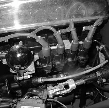
The next job was to modify the TR4A intake for injectors. I bolted the intake manifold onto the side of a length of large angle iron using the head end dowel pin holes. When the angle iron is placed like an upside-down “V,” it positions the manifold at 45° so that the head end is down and the carb end is up. I used progressively larger bits in my drill press to make ¾ inch diameter holes very near the head end by the flange. The injector bungs were purchased online, and the inside is already pre-machined for standard 14mm injectors. You just cut them to length and weld or epoxy them in place. I used aluminum “welding” rod I bought many years ago of the kind often shown at car shows and swap meets closing up holes in pop cans and small aluminum engine parts. You can Google Muggyweld or Durafix. The rod melts at a lower temperature than the aluminum parts do, so it is more like soldering or brazing in that respect. I didn’t want to epoxy and didn’t want to pay for TIG welding.
I bought a 14-inch length of fuel rail and a 17/32 drill bit and made a fuel rail to match the spacing of the holes in the manifold. I researched fuel injectors, as going too small or too large are equally bad. There are a number of online calculators for this. I ended up with a Bosch 0280150901. These are used on early 90’s GM 3.8 V6 engines, so they are common enough. They flow 18.55 lbs. per hour, which is close to what a TR3 engine needs. Too small and you lean out at high RPM and burn pistons. Too big and you can’t adjust the open time short enough to avoid flooding the engine at idle.
I did some math, and the total area of 2 SU carburetor throttle plates is slightly larger than one 62mm throttle, so I went online and found an inexpensive 62mm 97 Honda Accord throttle body. Same as the injectors, you don’t want it too big or too small, but for different reasons. I also bought a Honda Throttle Position Sensor (TPS) for this throttle body. I was looking for a throttle body that used a cable and had a progressive pulley so that the effective diameter changes as the throttle opens, making it less touchy just off of idle.
Since I was going to do full sequential on both injection and ignition, I decided on using 4 GM LS2 spark coils. These are 5-volt logic triggered and do not require any special circuitry in the Megasquirt. I also found these online. I made a bracket that bolts to where the original coil went to mount the coils on. Plugs are yttrium tip, gapped at .050 inch, which are the same ones I previously used for the Megajolt.


The “36-1” toothed crank wheel is from a Ford Escort 1.9L engine and was very easy to modify for the Megajolt ignition system. The downside is that it is for a serpentine belt. I wanted to change from the ¾ inch belt anyway. I had to make a water pump pulley to fit the serpentine belt. Moss has a similar replacement water pump pulley for their supercharger kit, but it was about $150, purchased separately, so that wasn’t an option for me. The alternator pulley you can buy. I had done this modification in 2009, so it saved a lot of time. You can also buy a 36-1 tooth wheel and weld or bolt it to your existing pulley if you want and skip the belt mods.
I bought a 4”x4” by 14” long square aluminum tubing with a ¼ inch wall thickness from Metals Supermarket for the plenum. It is bolted from the inside to the intake manifold where the carburetors would normally go. The theory is that it should be equal in volume to two or three times the displacement of the engine. The engine is around 130 cu. in., and the plenum is around 170, but this was the closest I could fit in the engine compartment. The end plates are 1/4 inch thick with the front one machined to mount the throttle body on. It is all screwed together with stainless steel hex drive screws. I wanted idle control, so I bought a 2”x2”x3” piece of aluminum and bored it out to adapt a GM Idle Air Control (IAC) valve to mount to the bottom of the throttle body where a Honda valve would normally go. Other sensors are coolant temperature, which is mounted in the thermostat housing, and intake air temperature, mounted in a threaded bung that was epoxied to a hole I drilled in the throttle body.
I ordered wiring at the same time as the Megasquirt kits. Each wire is labeled and color-coded for each function, making it a lot easier to keep track of. Once all of the hardware was positioned, I could cut the wires to length, install the ends, and then form them into bundles. Much of the online information alluded to the fact that you must route the sensor wires in such a way to avoid picking up electrical noise from other wires. To that end, I routed the injector wires and the ignition wires each in their own bundle. The sensor wires each have grounded shields, and they can be run together. All the return grounds and shield grounds go to a common point and then to the Megasquirt ground.
There are a couple of test boards you can optionally purchase, called JimStim, to test most of the functions of the Megasquirt before it is even installed in a vehicle. They plug into the Megasquirt where the wiring harnesses would normally go. It has potentiometers you turn to simulate things like coolant/air temperatures, O2 sensor output, and throttle position. It generates crank and cam sensor pulses also. You plug it in and then watch the results on the TunerStudio software. This software is then used to tune the Megasquirt to your particular engine.
The other things I worked on at home on the weekends were to plumb a new fuel line from the tank to the high-pressure pump and filters to the fuel rail at the engine. The existing line is reused as the return line from the fuel pressure regulator. My fuel tank had a drain plug installed from the factory, I presume, that had never been removed since the car was new. I drained and removed the tank to better see what I was doing. After removing the drain plug, I saw that the thread size was 5/8-16 and by chance, so is a 3/8NPT except it is tapered. I rethreaded the hole for a pipe thread and put in a shutoff valve followed by a TEE to connect to the fuel pump. The TEE lets me retain the draining function. The fuel pump is a Ford external pump used in 80-something vans and pickup trucks. I put in a pre-filter to protect the pump and a high-pressure filter after the pump to protect the injectors.
Since my TR3 had the bulkhead cover plate on the right side that covers the hole where the brake and clutch master cylinders would go on a right-hand drive car, I made a similar plate and mounted the Megasquirt ECU on the passenger compartment side of the plate as it is not made to stand up to heat of the engine compartment. Then, I ran all the wiring into the engine compartment using a 22 conductor Weatherpack bulkhead connector.
Once all the wiring, plumbing, throttle linkage was connected, the only left was to try and start it. You cannot start with what is called a blank Tune. You have to go through every setting in TunerStudio and make changes specific to your particular setup, following logical steps before you can attempt a start. Having done all this, I was able to attempt a start and did get it running the first time but it would not idle. As far as fuel goes, the most important table in Megasquirt is the VE table. VE stands for Volumetric Efficiency. The data is in a 16 by 16 matrix form that represents injector pulse widths at particular RPMs and engine loads that Megasquirt uses to try to stay at the required air-fuel ratio. There is also a similar 16 by 16 table for ignition timing with the same X Y axes as for fuel but the data represents the actual ignition advance values. This table is best tuned on a dyno but I just tried to emulate the published TR3A advance curves.
Back to fuel, with the engine and TunerStudio running it is easy to see what part of the VE table Megasquirt is currently referring to and you can make changes while the engine is running and see if you are doing any good or not. If you opt for and pay a nominal fee for the registered version of TunerStudio, it has a function called VE Analyze that will auto-tune as you drive. With the engine running as long as I held the throttle down a bit I turned on the VE Analyze and saw I was running lean and that the numbers in the table should be closer to 60 instead of 30 like they were around the idle area. I shut the engine off and changed all the idle area data to 60 and restarted the engine and it would finally idle.
Eventually, by watching the AFR gauge and tweaking the table, I was able to drive it around the block. I turned auto-tune back on and went for a longer drive and let it do its thing. This was pretty much all I had time for before I attended the 2013 TRA convention in Kentucky. I still have warm-up issues as it tends to bog down a bit when you punch the throttle when cold and have been working on that as time permits.
TRIUMPH Lifts and jacks etc
John Warfield - an expert on early TR toolkits - provides insight into the Prima branded bottle jack style tools.
by John Warfield
Most of us are fairly familiar with the types of jacks issued during the four-cylinder TR production run, and to some extent, the chronology of the changes made to these jacks. In the case of the most common type of jack (Part Number 110774) introduced at TS5469, the exact sequence and timing of design changes has never been firmly nailed down, and though there is a rough understanding of the succession of these changes, even in this there are supportable opposing views. Concours judges have been wise to avoid being too particular in judging jacks, as it is also highly likely that the issue of one type might have been running simultaneously with that of another, and they function the same.
Through the years, a number of undisturbed TR jacks have been recovered that were clearly painted black when new. As these were far less common than those painted orange-red, the prevailing wisdom has always been to paint these jacks range-red when restoring them to avoid potential controversy and deductions during concours events. I’ve done it any number of times. This, however, might have been unnecessary in some cases. Having been through a concours restoration of an XK150 some years ago (an unmitigated long-term nightmare), I was well aware that some of the jacks issued with these cars had been painted black. Little was known about them except that they were manufactured by Prima Industries Limited and had a transfer that very seldom survived beyond a few traces of glue. Having seen traces of glue on undisturbed black-painted TR jacks, I was of course intrigued. Did any of our jacks have Prima labels?
A few years ago, an article appeared in the XK Club’s XK Gazette by Roger Payne, a very well-respected Jaguar tool authority. In the article, the various XK jacks were sequentially described. In the XK150 section, there it was – a photo of a black-painted jack with a vertically oriented black label with large yellow letters spelling ‘PRIMA’. This jack was apparently introduced in April 1960, although earlier red-painted Prima jacks with horizontally oriented labels (also black and yellow) had been issued to these cars since mid-1958. All of the Prima jacks lacked the stamped manufacturer’s name and patent numbers present on earlier Smiths’ and B.T.C jacks and all of them possessed the separate beveled washer at the top of the tube to support the drive head rather than the Smiths’ patented annular groove that held the drive screw’s upper race to the tube. The black-painted TR jacks that I’ve encountered through the years all shared this later configuration. There had to be a connection.
The smoking gun appeared on eBay. A black-painted NOS TR jack was offered with a complete horizontally oriented PRIMA label. I didn’t hesitate to buy it. When it arrived, the jack was confirmed as undisturbed, and was sent to a graphics outfit for the purpose of reproducing the label. This has been done, and the reproductions are excellent. One is actually used on the jack in the photo, as the original was lost after the reproductions were made. As seen in Figure 1, the jack is painted black all over, has the beveled washer supporting the drive head, and the horizontal label featuring the manufacturer’s name, ‘PRIMA’ in plain yellow letters, along with ‘GUARANTEED’ and ‘BRITISH PRODUCT’ in smaller yellow letters above and below the manufacturer’s name. There were no patent numbers.
Clearly, Prima manufactured jacks for Standard-Triumph, and the evidence suggests they were introduced during the mid to late TR3A run. What we don’t know for certain is how long these black jacks were issued with TRs. We also don’t know whether Prima jacks were issued exclusively during the period they were supplied to Standard-Triumph, or whether some of these Prima jacks might have been painted red. Undisturbed red-painted jacks TR with the beveled washers have been discovered over the years (some with cast lifting hooks), and though I’ve yet to see a Prima label on one of these jacks, the survival rate of these labels is extremely low, and some had residue that might have been traces of glue. There might also have been TR jacks with vertical transfers, but I’ve yet to encounter any evidence that there were.
Clearly, we have enough information to answer one question, but in so doing, we’ve raised others. I wouldn’t be surprised if any of the above possibilities panned out, and wouldn’t deduct for either a red or black-painted Prima jack in a late TR3A and perhaps even 4-cylinder TRs of later vintage. We simply haven’t nailed all of this down. So those of you with late TR3As, 3Bs, and 4s, with jacks of known provenance, check them out closely, and if they are black, don’t be in a rush for a Chevy Engine Red spray-bomb.
Re-Braking a TR3B
Stan Seto showcases his project of converting the old Girling style front disc brakes into something more modern, safe, and better to maintain.
by Stan Seto
Follow these instructions at your own risk. The braking system on your car must function correctly to avoid serious injury; if you do not feel competent to do these modifications correctly, please either stick with the stock brake system or have a professional do the work for you.
Introduction:
It started with a stop…. A bad stop, the car halfway out in the intersection and everyone around, staring. Get on the brakes late after a long steady drive, pedal goes halfway to the floor and That’s What You Get! The ‘3 is an otherwise nice car to drive, accelerates well, runs through curves and corners without upset, it just does not STOP all that well. The bad stop got me thinking about improvement. Briefly considered rear discs, may still consider that, but in general more work than I care to get into. So what can be done in front??
Talked with Brother Russ who rebuilds Triumphs (TR Shop in Houston, TX). He sent me an article: Four piston brake caliper conversion for TR3 to TR6. Written by R. John Lye and Lee Janssen, it was published in The Vintage Triumph, Issue 76, available on the web from:
http://www.vtr.org/maintain/brake-conversion.shtml
The gist of the article (which concentrated on re-braking a TR6) was that this is not all that hard to do. The ingredients were brake calipers from a Toyota light truck (vintage 1979 to 1983), new brake lines, new bolts, some minor surgery on the dust shields and there you have it. I did have to read the article a number of times to ensure I understood the work to be done on the TR3 as opposed to that on the TR6, and ferret my way through the jargon and inverse thinking of the authors, but finally convinced myself I could do this.
So, what first?
Parts, availability, and cost! One Saturday morning I took off to an O’Reilly’s Auto Parts store near me (Auto Zone, KOI, Smyth, and other vendors were equally close), but in our TR outings, it seemed to me that O’Reilly’s always seemed to have what was needed. The lady at the Parts counter heard my request and started searching her online files (Diesel or non-diesel? Non-diesel), (Four-wheel Drive? Yes.), (What years? ‘79 to ‘83.)….. Well, there was one caliper part that carried through, so she pulled it up and it looked right. Price? - $42.00 and core charge, each. Brake lines? No, we don’t have those, go to Ohio Hydraulics. I knew where that company was. Called The Roadster Factory and asked for the STANPART number in the article, confirmed they were 12mm with SAE threads, and $9.95 each. TRF had some in stock. Ordered two new front brake lines for the ‘3.
During the week, went to Ohio Hydraulics, just off Kemper Road in Sharonville, OH. The brake lines are to be SAE fitting (7/16) and thread (24) on the end that attaches to the chassis and metric (10X1.0, inverted flare fitting) where it screws into the caliper. The Toyota caliper hose location was on the side of the caliper, so a 90-degree fitting was required. The Girling caliper on the car was a radial screw-in (straight down) so it can be straight at each end. Because I was not sure where the new caliper fitting was relative to the Girling caliper fitting, I made the decision to go with all new brake lines and slightly longer than the current. It was an OK decision and cost me about thirty dollars more than refitting the TRF lines, but rather too long than too short. Ohio Hydraulics could not find a metric fitting in a right-angle shape. We did find the fitting needed in an adapter. The final solution was an SAE fitting on one end of the hose, total length one inch more than the current hose, SAE right-angle fitting on the other end of the hose, and an SAE to Metric adapter.
Bought the calipers and a regular pad set. Can upgrade pads later. Bought the bolts and hoses. Took it all home and the next weekend, warm and sunny, put the front of the car up on blocks and disassembled the passenger’s side brake system. Started by putting plastic wrap over the top of the brake-clutch reservoir and screwing the top back on to minimize fluid loss. Broke the brake line at the chassis, pulled the caliper bolts and lock washers, and removed the caliper. Took the brake line off the caliper, removed pads, and put pad retention hardware back on the caliper (my core). Removed the nut and lock washer holding the dust shield to the support. Cleaned up all the parts removed. Everything was SAE 7/16 – 24. Recut the threads on the shield nut, as they were rusted.
Took a minute and went to Sears and bought new split ring lock washers (Grade 8) for all bolts. The brake lines at the chassis had anti-shake lock washers. Found them at Lowe’s, not Grade 8, but Grade 5.
Okay, Let’s Start!
Back home, got out rotary tool (Sears, but Dremel would also do) and put a radiac wheel on it. Pulled the dust shield to a comfortable position, slid a piece of corrugated cardboard in between the shield and the brake disc, and carefully removed 3/10 of an inch of material from both sides of the shield that are closest to the caliper to make room for the new caliper. The three-tenth measurement was in a circumferential direction and from the middle of the current shield edge, and the cut line was radial, inner to outer. Both cuts took me about ten minutes each. The cardboard held the shield away from the disc surface and gave indication when the radiac wheel penetrated the inner surface of the shield.
I removed the radiac wheel and put in a metal cutting burr. Again with care, I used the burr to open up the holes in the shield that the caliper bolts had to go through to clamp the shield and the caliper to the support arm. Those holes are 7/16ths (0.4375 in.) and have to be opened to 12 mm (0.4716 in.), a matter of about 0.0341 inches on the diameter. Takes about 2 minutes a hole.
Took a couple of files (flat and rat tail) and filed all the cut edges smooth, getting rid of any lingering flash. Now ready to assemble things.
The Toyota caliper drops straight in. The bolts with lock washers reposition the dust shield, and the caliper support plate has threads recessed about a tenth of an inch, so the bolts self-center and getting the thread engaged was easy. Wound the bolts down snug and then put the washer and nut back on the shield support. Tightened those three items. There is no torque called out for the caliper bolts, so I leaned on them with a long-handled ratchet.
Attaching the hose to the caliper: a caution here. The caliper is all aluminum. The hose fittings are steel. The thread is UNF. DO NOT OVER TIGHTEN the hose fitting. If you strip these threads, it will cost you! I lubricated (brake fluid) and installed the metric adapter into the caliper and tightened. Then lubricated and screwed the SAE right-angle fitting into the adapter. Got it snug but not tight. Then I screwed the other end of the hose into the chassis hard line, again lubricating the threads. That line I tightened. I then had a neighbor turn the steering wheel so I could check clearance relative to the car body work and the hose in the caliper. There was some touching at full lock. I adjusted the hose at the caliper until I had sufficient clearance and then tightened that line into the adapter, holding the adapter with a wrench while I tightened the fitting.
Installed the brake pads and was done with the mechanics of the job. Doing the first side took about an hour and a half because I worked slowly. I did the other side in about forty minutes.
Bled the brake system and was done except for testing. Took the car out for a spin around the neighborhood. Brakes worked fine. Now for five hundred miles of pad break-in.
I did measure the brake pad area. The Girling pads have five square inches of area, and the Toyota pads have just over six and four-tenths square inches, a net increase of 26%.
So, what did it cost?
The calipers (O’Reilly part No. 19-820 and 19-821) were $42.99 each plus core charge ($25.00). Total cost - $85.98 plus state tax.
• The pad set (very standard), part No. D137 was $13.99.
• The Caliper Bolts from The Roadster Factory, Part No. 158668, were $9.91 each, four required. Total cost was $39.64.
• The Hoses were $37.56 each, and the adapters were $4.30 each. Total cost was $83.72, but if I had stuck with the normal TR-3 hoses and just changed the one end, then the total cost would have been about $72.00.
• Miscellaneous hardware (new washers, etc.) and grease for pads, total cost - $7.68.
All up cost was $231.01. Installed and ready to stop!
**Postlude**
I pretty much broke the pads in during the Fall Leaf Tour, and this past weekend the club did the Guy Fawkes Tour for another 200 odd miles. On the return home (32 miles) on a cold and starry night, and beating down Rte 42 from Lebanon to Hopkinsville, I had occasion to do four hard stops from 60 – 70 MPH to stopped at some traffic lights (8 total, hit yellow to red on four, one simply for a car that was making a left turn across our lane) and the car came down quickly and in a very short distance (and I might add the tires, Vredestein Sprint Classics, are new this year). So these new calipers are a lot better than the Girling’s which were removed. This is a relatively inexpensive, and quick conversion that will really enhance a TR-3, -4, or -6 stopping performance. I’d bet it would work equally well on a Morgan.


Behind the scene dashboard improvements
Douglas Jack provides helpful insight on how to work behind the dash without all of the discomfort.
by Douglas Jack
"Have you ever had your hand in the never, never region behind a TR dashboard with the intent of reaching the round nuts holding the bracket to either the tachometer or the speedometer, only to find that the nuts are very, very tight against the bracket and that your fingers cannot unloosen them?"
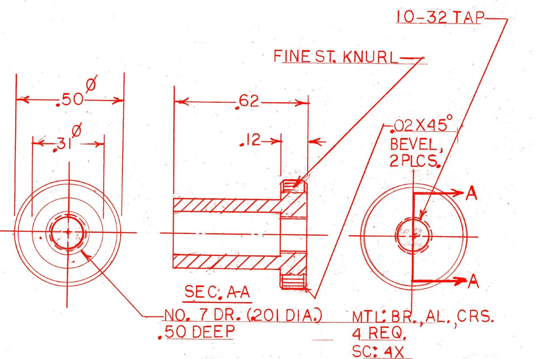
As shown in the picture, here is a simple trick to alleviate this problem. It is a brass spacer, 5/16 in O.D. x 1/4 in I.D. x 1/2 in long. Any material may be substituted for the brass one (I happened to have a short piece of tubing). Installing the nuts and spacers will enable you to have a better grip on the nuts. With the spacers in place, removing the nuts will also be easier. It will be helpful to run a tap through the nuts and also chase the threads on the instruments for greater success in the future. For those who have access to a metal turning lathe or a machine shop, here is an alternate one-piece design that will also make it easier to install and/or remove the nuts with only one hand. I hope you find this tip helpful.
Douglas A. Jack